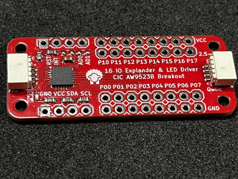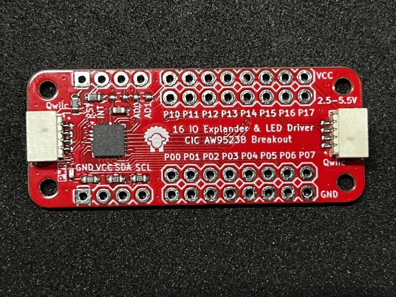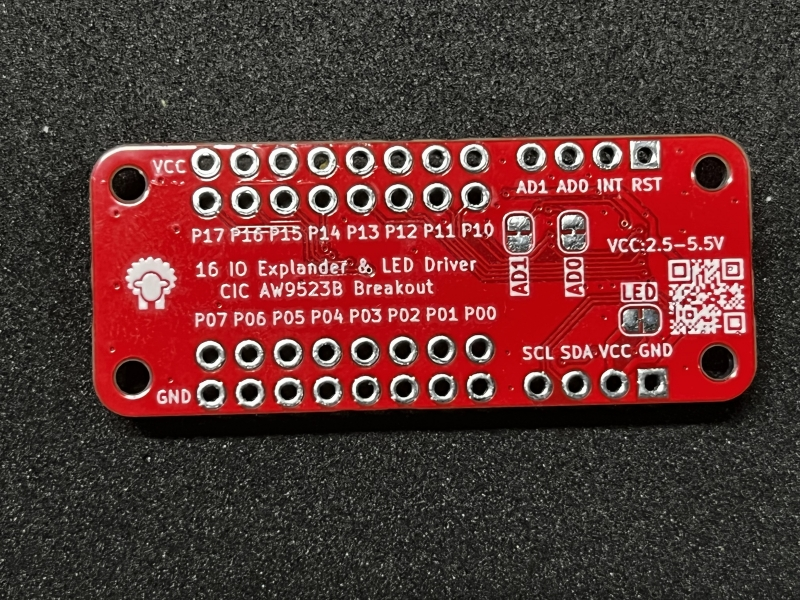
CIC AW9523B Breakout - 16 IO Explander & LED Driver
Overview
AW9523B is a 16 multi-function LED driver and GPIO controller. Any of the 16 I/O ports can be configured as LED drive mode or GPIO mode.Furthermore, any GPIO can be configured as an input or an output independently.
After power on, all the 16 I/O ports are configured as GPIO output as default, which default states areset according to the I2C device address selectioninputs, AD0 and AD1. All I/O ports configured as inputs are continuously monitored for state changes. State changes are indicated by the INTN output. When AW9523B reads GPIO state through the I2C interface, the interrupt is cleared. Interrupt has 8μs deglitch.
When the I/O ports are configured as LED drive mode, AW9523B can set the current of LED drive between 0~IMAX by I2C interface, which is divided by 256 steps linear dimming. The default maximum current (IMAX) is 37mA, and IMAX can be changed in GCR register.


Features
- 16 multi-function I/O, each for LED drive (current-source dimming) or GPIO mode
- 256 steps linear dimming in LED drive mode
- Any GPIO can be configured as an input or an output independently
- Support interrupt, 8μs deglitch, low-level active
- Standard I2C interface, AD1/AD0 select I2C device address
- SDA, SCL, RSTN, and all GPIO can accept in 1.8V logic input
- Supply shutdown function, low-level active 2.5V~5.5V power supply
Specifications
- AW9523B - a 16 multi-function LED driver and GPIO controller
- Headers for P0, P1, VDD, GND, easy to use
- Headers for I2C, VDD, GND, Reset & AD0/1, easy to connect with MCU
- Qwiic connector x 2, easy to debug & use
- Dimension: 44 x 18 x 5 mm
Hardware

| Pin | Description | Note |
|---|---|---|
| GND | Ground | |
| VCC | Power Suppy 2.5-5.5V, for example 3.3V | |
| SDA | I2C interface Data bus | Had external pull-up resistor 4K7 |
| SCL | I2C interface Clock bus | Had external pull-up resistor 4K7 |
| RESET | Hardware Reset Pin, Low Reset | Had external pull-up resistor 10K |
| INT | Interrupt pin output, Open-Drain mode, Active low | Had external pull-up resistor 10K |
| AD0 | I2C interface device address bit0 | Default 0 |
| AD1 | I2C interface device address bit1 | Default 0 |
| P00-P07 | GPIO mode default, input or output, open-drain (default) or push-pull mode. Can be configured as LED drive mode | |
| P10-P17 | GPIO mode default, input or output, push-pull mode. Can be configured as LED drive mode |
Default I2C interface 7 bit device address: 0x58
User Guide
It is the best choice to develop embedded drivers with embedded rust. Because the driver can be used with MCU like ESP32, also used with ARM64 Linux Application, for example raspberry pi directly.
You can download the aw9523b rust driver with git, also add your rust project with cargo - cargo add aw9523b.
The examples as below use the first one.
git clone https://github.com/xpulabs/aw9523b-rs
Examples
GPIO Mode - Input
This example will config aw9523b's P00 as input, and read the pin level. If the pin level is high, Console will print "P00 is high".
use linux_embedded_hal::I2cdev;
use aw9523b::Aw9523b;

fn main() {
    let dev = I2cdev::new("/dev/i2c-3").unwrap();
    let mut ic = Aw9523b::new(dev, 0x58);

    let id = ic.id().unwrap();
    println!("aw9523b id = {:02x}", id);
    std::thread::sleep(std::time::Duration::from_secs(1));

    ic.set_io_direction(aw9523b::Pin::P00, aw9523b::Dir::INPUT).unwrap();

    loop {
        while !ic.pin_is_low(aw9523b::Pin::P00).unwrap() {
            println!("P00 is high");
            std::thread::sleep(std::time::Duration::from_millis(200));
        }
        println!("P00 is low");
    }
}
/dev/i2c-3is a i2c controller of rpi.- The AW9523B's I2C Device address is 0x58. So we use
newfunction to create a instance.Aw9523b::new(dev, 0x58) set_io_directionfunction will set theP00as Input- In the loop, we always read the pin level and check the pin is low or not.
pin_is_low
Use the command as below to build and run the app.
cargo build --target aarch64-unknown-linux-gnu -- example linux-gpio-input
scp -r ./target/aarch64-unknown-linux-gnu/debug/example/linux-gpio-input rpi@192.168.6.77:
After login the RPI with SSH, we can execute the app directly.
sudo ./linux-gpio-input
The terminal will print the level of P00.
GPIO Mode - Output
This example will config aw9523b's P00 & P10 as output, and set the pin level high or low. If the pin is connected with LED, the LED will ON or OFF.
use linux_embedded_hal::I2cdev;
use aw9523b::Aw9523b;

fn main() {
    let dev = I2cdev::new("/dev/i2c-3").unwrap();
    let mut ic = Aw9523b::new(dev, 0x58);

    let id = ic.id().unwrap();
    println!("aw9523b id = {:02x}", id);
    std::thread::sleep(std::time::Duration::from_secs(1));

    ic.port0_output_mode(aw9523b::OutputMode::PP).unwrap();

    loop {
        println!("P00 set high");
        ic.set_pin_high(aw9523b::Pin::P00).unwrap();
        std::thread::sleep(std::time::Duration::from_secs(1));
        println!("P00 set low");
        ic.set_pin_low(aw9523b::Pin::P00).unwrap();
        std::thread::sleep(std::time::Duration::from_secs(1));

        println!("P10 set high");
        ic.set_pin_high(aw9523b::Pin::P10).unwrap();
        std::thread::sleep(std::time::Duration::from_secs(1));
        println!("P10 set low");
        ic.set_pin_low(aw9523b::Pin::P10).unwrap();
        std::thread::sleep(std::time::Duration::from_secs(1));
    }
}
/dev/i2c-3is a i2c controller of rpi.- The AW9523B's I2C Device address is 0x58. So we use
newfunction to create a instance.Aw9523b::new(dev, 0x58) - AW9523B Port0 has two ouput mode - Push Pull and Open Drain, the default mode is Open Drain, So we need use function
port0_output_modeto change the mode to Push Pull. - In the loop, we always set the pin level high or low after a delay with function
set_pin_high&set_pin_low.
Use the command as below to build and run the app.
cargo build --target aarch64-unknown-linux-gnu -- example linux-gpio-output
scp -r ./target/aarch64-unknown-linux-gnu/debug/example/linux-gpio-output rpi@192.168.6.77:
After login the RPI with SSH, we can execute the app directly.
sudo ./linux-gpio-output
The LED will ON, after a delay, will OFF.
LED Mode
This example will config aw9523b's P00 & P17 as LED mode to driver a LED directly, and LED Dimming.
use linux_embedded_hal::I2cdev;
use aw9523b::Aw9523b;

fn main() {
    let dev = I2cdev::new("/dev/i2c-3").unwrap();
    let mut ic = Aw9523b::new(dev, 0x58);

    let id = ic.id().unwrap();
    println!("aw9523b id = {:02x}", id);
    std::thread::sleep(std::time::Duration::from_secs(1));

    println!("aw9523b led mode: dimming");
    ic.pin_led_mode(aw9523b::Pin::P00).unwrap();
    ic.pin_led_mode(aw9523b::Pin::P17).unwrap();

    ic.led_dimming_range(aw9523b::DimmingRange::IMAX).unwrap();

    loop {

        for i in 0u8..255 {
            ic.led_set_dimming(aw9523b::Pin::P00, i).unwrap();
            ic.led_set_dimming(aw9523b::Pin::P17, 255-i).unwrap();
            if i < 200 {
                std::thread::sleep(std::time::Duration::from_millis(10));
            } else {
                std::thread::sleep(std::time::Duration::from_millis(100));
            }

        }
    }
}
/dev/i2c-3is a i2c controller of rpi.- The AW9523B's I2C Device address is 0x58. So we use
newfunction to create a instance.Aw9523b::new(dev, 0x58) - AW9523B's pin mode is GPIO, we need to change to LED mode with function
pin_led_mode. - Using function
led_dimming_rangecontrol the LED current globaly. - In the loop, we always set the LED current level from 0 to 255 with function
led_set_dimming.
Use the command as below to build and run the app.
cargo build --target aarch64-unknown-linux-gnu -- example linux-led-mode
scp -r ./target/aarch64-unknown-linux-gnu/debug/example/linux-led-mode rpi@192.168.6.77:
After login the RPI with SSH, we can execute the app directly.
sudo ./linux-led-mode
The video will display the LED Dimming.
Buy it Now
Resources
Documents
Codes
3D Drawing
TBD
FAQ
TBD